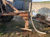
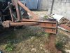
Finally have the mole plough near finished just needs a disc added . Thanks
@muckymanor & @jackc for the measurements . Did a neat enough job with no disc today on a trial run . With only one issue arising. Had only a 20 mm bolt and a length of 20 mm threaded bar as pins holding on the leg . First big stone and threaded bar snapped resulting in the leg going back and breaking through the back plate . Back plate trimmed and using 20mm steel bar . It worked away fine . But the bar got fair abuse and not a long term solution. Question is should I keep using mild steel bar for the pins as a sort of break away or lock it up solid. Is there a breakaway on the proper ones ? Blade still has to be able to move up or down for different depths .